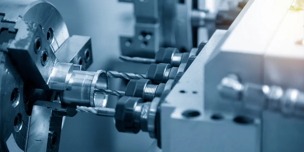
How to perform milling using a CNC milling machine
For beginners, CNC milling may seem like “input program → machine automatically processes”. However, in actual operation, each step has a clear sequence and control points.
Any error in any step will directly affect the quality of the parts, and may even lead to their scrapping.
Basic operating procedures
Below is a standard basic CNC milling process (simplified version, but consistent with actual production logic):
1. Prepare the CAD model
- Create or import 3D models (STEP / IGES formats, etc.)
- Confirm the dimensions, tolerances, and structural suitability.
If the model itself has problems (such as unmanufacturable structures), no amount of subsequent processing can make up for them.
2. CAM programming (generating toolpaths)
Import the model into CAM software and perform toolpath planning:
- Choose a processing strategy (roughing/finishing)
- Set the cutting tool (size, type)
- Define cutting parameters (speed, feed)
This stage determined:
- Processing time
- Surface quality
- Tool life
3. Output G-code
The post-processor converts the toolpath into machine-readable G-code.
Different machine tool systems (such as Fanuc and Siemens) have different formats, which must be matched.
4. Machine tool setup
Before the actual processing begins, a series of preparatory work needs to be completed:
- Install the cutting tool
- Fix the workpiece (clamping)
- Set the workpiece coordinate system (tool setting)
- Input or import program
This is one of the stages most prone to problems in actual operation.
5. Dry Run
Before the actual cutting, a no-run check is usually performed:
- Check if the toolpath is correct.
- Confirm that no collision will occur
- Verify program logic
This step is crucial when you lack experience, as it can prevent you from scrapping the workpiece.
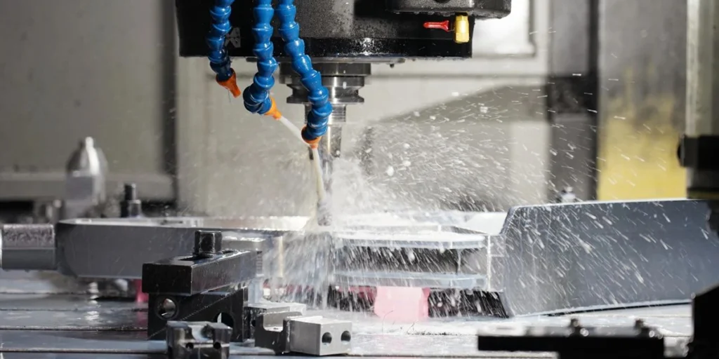
6. Formal processing
After confirming that everything is correct, begin cutting:
- Monitor cutting status (sound, vibration)
- Inspect the condition of the chips.
- Pay attention to tool wear
The processing is not “completely automatic” and still requires human intervention and judgment.
7. Testing and Adjustment
After processing:
- Measure critical dimensions
- Inspect surface quality
- Compensation or secondary processing will be carried out if necessary.
How to machine parts using a CNC milling machine
Transforming a CAD model into a real part is not simply a matter of executing a program. The real challenge lies in controlling errors, stabilizing results, and avoiding repeated trial and error at every stage.
For inexperienced teams, “being able to process” and “processing stably” are two completely different things.
From blueprints to finished product
Below is a breakdown of the process that is closer to actual production, rather than a theoretical step.
1. Analyze the drawings (instead of directly manufacturing them).
The first step after receiving the blueprints should not be programming, but rather making judgments:
- Are there any unmachinable structures (such as deep narrow grooves or acute interior angles)?
- Are the tolerances reasonable (is there any unnecessary high precision)?
- Is there a design that can be optimized (reducing steps or clamping)?
Many beginners skip this step and go straight to CAM programming, resulting in:
- Processing difficulty is amplified
- Unnecessary cost increases
- There are even cases where processing is impossible.
The mature approach is to optimize first, then process.
2. Process planning (determines the overall strategy)
Before programming, the processing strategy needs to be determined:
- Whether to clamp in multiple stages
- Is 5-axis machining required?
- How should roughing and finishing be allocated?
- Which areas should be processed first (to avoid deformation)?
This stage determined the entire project:
- Processing time
- Precision controllability
- Yield
The problem with many low-priced suppliers lies here: they lack process planning and simply follow the established procedures.
3. Programming and Path Optimization
Once in the CAM stage, the focus shifts not only to “generating paths” but also to optimizing them.
- Control the cutting load (avoid tool overload)
- Reduce empty trips
- Optimize tool feed method
The same part, different paths may lead to:
- Several times the time difference
- Completely different surface quality
This step relies heavily on experience, rather than the software itself.
4. Clamping and Datum Establishment
Next, we will enter the actual processing preparation stage.
The key question is: how to define the machining datum.
- Incorrect baseline selection → All subsequent dimensions will be off.
- Unstable clamping → May shift or deform during machining.
For complex parts, typically:
- Design special fixtures
- Unified reference surface
- Phased clamping
This step often determines the final upper limit of accuracy.
5. Processing in stages (not completed all at once)
In actual manufacturing, it is rare to complete all the structures in one step.
Typical process:
- Rough processing → Rapid material removal
- Semi-finishing → Adjusting allowance
- Finishing → Dimensional Control
For high-precision parts, the following may also be added:
- Secondary finishing
- Local correction and processing
The sole purpose of this is to disperse errors rather than concentrate them into a single burst.
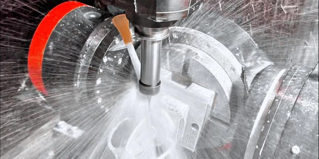
6. Process monitoring (overlooked but crucial)
Many people think CNC is “automation”, but in reality:
- The blade will wear out.
- The state of the material will change.
- Temperature affects size
Therefore, the following is required during the processing:
- Check critical dimensions midway through the process
- Monitor tool status
- Adjust parameters if necessary
Otherwise, it may happen that the first few items are acceptable, but all the later ones are not.
7. Final Inspection and Delivery
After processing is complete, the following confirmation is required:
- Are the dimensions within tolerance range?
- Does the surface quality meet the standards?
- Are there any burrs or defects?
For high-demand industries, the following is also required:
- Test report
- Batch traceability
Common Mistakes and Risks
In practice, the problem often doesn’t stem from a lack of processing skills, but rather from overlooked details. These errors may not be obvious at first, but they amplify rapidly once mass production begins, directly leading to:
- Size instability
- Surface quality deteriorates
- Mass scrapping
Below are the two most common, and also the most easily underestimated, types of problems.
Incorrect tool selection
Knives are not universal; “can cut” does not mean “cuts well”.
1. Tool type mismatch
Different materials and structures place specific requirements on cutting tools:
- Aluminum parts → Typically require high-sharpness cutting tools
- Stainless steel → Tools requiring wear-resistant coating
- Curved surface structure → Commonly used ball end mills
Common consequences of choosing the wrong cutting tool include:
- Cutting is not smooth (vibration occurs)
- Rough surface
- Extremely low processing efficiency
2. Inappropriate tool size selection
Tool size directly affects machining stability:
- Overly long cutting tool → Poor rigidity, prone to vibration
- Tool too small → machining time increases significantly
Especially in deep cavity or narrow groove structures, if the tool length and diameter are not properly matched, the following problems can easily occur:
- Side knife
- Dimensional error
- Uneven surface texture
3. Neglecting tool wear
The cutting tool is not in a constant state. As machining progresses:
- Tools will gradually wear down.
- The cutting force changes
- Size begins to shift
Without a monitoring mechanism, a typical problem will occur: the first few items will pass inspection, but subsequent batches will exceed tolerances.
A mature processing procedure typically includes:
- Configure tool life management
- Replace cutting tools regularly.
- Compensate for critical dimensions
Clamping problem
Compared to cutting tools, clamping is more easily overlooked, but its impact is more direct.
1. Unstable clamping
If the workpiece is not securely fastened:
- Minor movement occurs during processing
- Causes dimensional deviations
- Surface textures
This type of problem is often difficult to reproduce, but it will be exposed during testing.
2. Inappropriate clamping force
Clamping is not a case of the tighter the better.
- Too loose a clamp → Workpiece moves
- Clamping too tightly → Workpiece deformation
Especially:
- Thin-walled parts
- Long strip structure
- Lightweight design components
If the clamping force is not properly controlled, the dimensions will change after the stress is released following machining.
3. Incorrect reference selection
This is one of the most insidious yet fatal problems. If the machining reference is chosen incorrectly:
- Errors accumulate at each stage of the process.
- Error amplified after multiple clamping operations
The forms of expression are usually:
- The dimensions are correct in some parts, but the overall size is mismatched.
- Problems occurred during assembly
4. Accumulated errors from multiple clamping operations
Complex parts often require multiple flipping processes. Without a unified datum or positioning strategy:
- Each repositioning introduces a deviation.
- The final dimensional chain went out of control
Optimization methods include:
- Unified positioning benchmark
- Use locating pins or special clamps
- Reduce the number of setups (e.g., use 5-axis machining)
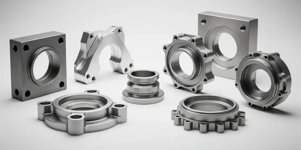
Why should you find a professional CNC milling manufacturer to process your parts?
For manufacturers like us who have long focused on CNC milling, the types of projects we actually handle are extremely complex—ranging from simple structural parts to high-precision, multi-faceted machining parts. That’s why, from the very beginning, we don’t just get involved in the “machining” process; we break down the problem for you first.
When many clients send us their drawings, our first step is usually not to provide a quote, but to take a look:
- Is there a simpler way to manufacture this structure?
- Is there any room to reduce clamping and lower costs?
- Is the tolerance setting reasonable?
These adjustments sometimes don’t change functionality, but they can significantly impact price and delivery time.
During the actual manufacturing stage, our focus is on “stability.” It’s not about producing a single, qualified part, but about ensuring that every part is produced to the same standard.
This relies on:
- Mature process pathway
- Reasonable clamping strategy
- Continuous control during the processing
These are things you can’t see on the blueprints, but they directly affect the final result.
Another practical issue is cost. Our optimization efforts typically don’t involve lowering prices, but rather through:
- Reduce unnecessary procedures
- Optimize toolpath
- Improve the first-pass yield
The goal is to reduce the overall cost of the project, rather than making the price of individual items appear cheap.
If you have parts that are currently being evaluated, you can send us the drawings directly, and we can take a look at a draft for you first.
- Are there better processing solutions?
- Is there room for cost optimization?
- And approximate delivery time and accuracy feasibility
Often, choosing the right direction before processing is more crucial than making repeated adjustments later.